MP Board Class 12th Physics Important Questions Chapter 4 Moving Charges and Magnetism
Moving Charges and Magnetism Important Questions
Moving Charges and Magnetism Objective Type Questions
Question 1.
Choose the correct answer of the following:
Question 1.
The magnetic effect of electric current was discovered by :
(a) Flemming
(b) Faraday
(c) Ampere
(d) Oersted.
Answer:
(d) Oersted.
Question 2.
A moving charge produces :
(a) Only electric field
(b) Only magnetic field
(c) Both electic and magnetic field
(d) Neither electric nor magnetic field.
Answer:
(c) Both electic and magnetic field
Question 3.
The SI unit of magnetic field intensity is :
(a) N/m
(b) Gauss or oersted
(c) N/A – m
(d) weber x metre .
Answer:
(c) N/A – m
![]()
Question 4.
Amperes circuital rule is :
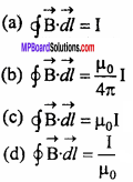
Answer:
![]()
Question 5.
The magnetic field produced at the centre of a circular coil carrying current is :
(a) In the plane of plane
(b) Perpendicular to the plane of coil
(c) At 45° from the plane of coil
(d) At 60° from the plane of coil.
Answer:
(b) Perpendicular to the plane of coil
Question 6.
The force on a charge moving in a uniform magnetic field is zero if the direction of motion of charge is :
(a) Perpendicular to the magnetic field
(b) At 45° from magnetic field
(c) At 60° from the magnetic field
(d) Parallel to the magnetic field.
Answer:
(d) Parallel to the magnetic field.
Question 7.
The torque on a current carrying loop in a uniform magnetic field is maximum when the plane of loop is :
(a) Parallel to the magnetic field
(b) Perpendicular to the magnetic field
(c) At 45° from the magnetic field
(d) At 60° from the magnetic field.
Answer:
(a) Parallel to the magnetic field
Question 8.
To measure the current in a circuit we use :
(a) Voltmeter
(b) Galvanometer
(c) Ammeter
(d) Voltameter.
Answer:
(c) Ammeter
Question 2.
Fill in the blanks :
- The SI unit of permeability is ……………..
- SI unit of magnetic field is ……………..
- Dimensional formula of magnetic field is ……………..
- A current carrying solenoid behaves like a ……………..
- The lorentz force on a charged particle in a uniform magnetic field is given as ……………..
- The force between two parallel conductors carrying current in same direction is …………….. in nature.
- The resistance of an ideal ammeter is ……………..
Answer:
- ampere2
- newton/ampere
- [MT-2 A-1 ]
- Bar magnet
- q\(\vec { (v } ×\vec { B) } \)
- Attractive
- Infinite
Question 3.
Match the Column :
I.
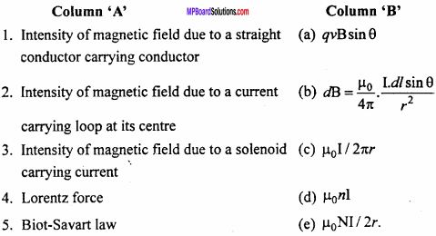
Answer:
- (c)
- (e)
- (d)
- (a)
- (b)
II.

Answer:
- (d)
- (e)
- (b)
- (a)
- (c)
![]()
Question 4.
Write the answer in one word/sentence
- State Ampere’s circuital law.
- Which material is used for the suspension wire of a moving coil galvanometer and why?
- What should be the resistance of an ideal voltmeter and ammeter?
- What happens if a voltmeter is connected in series to the circuit?
- What is a cyclotron?
- What do you mean by magnetic effect of current?
- State Maxwell’s right – hand screw rule.
- What happens if a voltmeter is connected in series to the circuit?
Answer:
1. Ampere’s circuital law states that the line integral of magnetic field \(\vec { B }\) around any closed path is equal to Mo times the total current I enclosed by the path. Mathematically \(\oint { \vec { B. } } \vec { dl }\) = µ0I
2. Phosphor bronze alloy is used as suspension wire because it has small restoring torque per unit twist and has a high tensile strength
3. An ideal voltmeter should have infinite resistance and the resistance of an ideal ammeter should be zero
4. The resistance of voltmeter is very high, therefore current will be decreased to almost zero
5. Cyclotron is a device used to accelerate positively charged particles (like protons, a particles). So that they can acquire sufficient energy to carry out nuclear disintegrations
6. When current is passed through any conductor, a magnetic field is produced around it. This phenomenon is called magnetic effect of current.
7. If a cork screw is turned so that it advances in the direction of current along the wire, then the direction in which the thumb rotates gives the direction of magnetic lines of force.
8. The resistance of voltmeter is very high, therefore current will be decreased to almost zero.
Moving Charges and Magnetism Very Short Answer Type Questions
Question 1.
Write practical unit of current and define it.
Answer:
The practical unit of current is ampere. One ampere of current is that current which produces a field of 10-7 Wb/m2, at the centre of the conductor of length 1m, placed in the form of an arc of a circle of radius 1 m.
Question 2.
Write S.I. unit of magnetic field intensity and define it.
Answer:
The S.I. unit of magnetic field intensity is newton / ampere x metre.
The intensity of the magnetic field is 1 newton ampere-1 metre-1. If 1 newton force acts on a conductor of length lm carrying a current of 1 ampere and held perpendicular to the magnetic field.
Question 3.
Write an expression for force acting on current – carrying conductor placed in magnetic field. Give the meaning of symbols used.
Answer:
The force on current – carrying conductor kept in magnetic field is given by :
F = IBl sinθ
Where, I = Current, l = Length of conductor, B = Field intensity and θ = Angle between the direction of magnetic field and the conductor.
![]()
Question 4.
What is the practical unit of current? Give its definition.
Answer:
If two parallel conductors situated at a perpendicular distance of 1 metre carry equal current in the same direction and exert an attractive force of 2 x 10⁻⁷ newton on each other in air or vacuum, then the current on each conductor is equal to one ampere.
Question 5.
Why a soft iron core is kept in moving coil galvanometer?
Answer:
The magnetic lines of force crossed through the soft iron core. This increases the magnetic field and hence sensitivity of galvanometer. The soft iron core helps to make the magnetic field radial.
Question 6.
The pole pieces of magnet are cut concave in a galvanometer. Why?
Answer:
So that the magnetic field becomes radial, hence the plane of the coil becomes parallel to the magnetic field. Under this condition, the deflecting torque on the coil is maximum.
Question 7.
What happens if an ammeter is connected in parallel to the circuit? What is the resistance of an ideal ammeter?
Answer:
The resistance of an ammeter is very less, hence almost all the current will flow through the ammeter which may damage the ammeter. The resistance of an ideal ammeter is zero.
Question 8.
Why an ammeter is connected in series in an electric field?
Answer:
An ammeter measures the electric current of the circuit, hence all the current should pass through the ammeter. Therefore, it is connected in series.
Question 9.
The resistance of ammeter should be very small. Why?
Or
The resistance of an ideal ammeter is zero. Why?
Answer:
An ammeter measures the current of an electric circuit, therefore it is connected in series. If the resistance of ammeter is large, then it will decrease the current in the circuit. Thus, the resistance of an ammeter should be less or zero.
Question 10.
What will be the resultant magnetic field intensity of point O as shown in the figure?

Answer:
Due to the straight portion of the wire the resultant field will be zero and due to semi circle. The resultant field intensity will be
B = \(\frac { { µ }_{ 0 }I }{ 4R }\)
Moving Charges and Magnetism Short Answer Type Questions
Question 1.
What is second right – hand palm rule? Write its uses.
Answer:
Stretch out the palm of your right – hand such that the fingers are perpendicular to the direction of thumb.
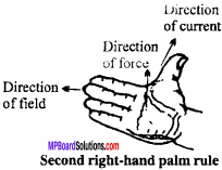
If the thumb points the direction of current and the fingers point the direction of magnetic field, then the force acting on conductor will be in upward direction perpendicular to Direction i the palm.
Uses:
By it’s we can find out intensity of magnetic filed due topufrent carrying conductor.
Question 2.
Write Biot – Savart law for the magnetic field produced due to an element of a current – carrying conductor and explain the term used in it. Define the unit of current with the help of it
Answer:
Let AB be a conductor carrying current I. Consider a small line element dl of the conductor, due to which the magnetic field dB is produced at point P, then the strength of the magnetic field \(\vec { (dB) }\) depends on the following factors :
1. The field is directly proportional to current I.
i.e., dB ∝I
2. The field is directly proportional to the length of element,
i.e., dB ∝ dl
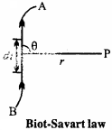
3. The field is directly proportional to the sine of angle between the line joining the point and dl.
i.e., dB ∝ sinθ
4. The field is inversely proportional to the square of the distance between the observation point and line element.
i.e.,
dB ∝ \(\frac { 1 }{ { r }^{ 2 } }\)
Combining all the four points,we get
dB ∝ \(\frac { Idl sinθ }{ { r }^{ 2 } }\)
or dB ∝ K\(\frac { Idl sinθ }{ { r }^{ 2 } }\) … (1)
Where, K is constant of proportionality. Its value depends upon the system of units
In C.G.S system, k = 1
∴ dB ∝ K\(\frac { Idl sinθ }{ { r }^{ 2 } }\) gauss … (2)
In M.K.S. system, K = \(\frac { { μ }_{ 0 } }{ 4π }\)
Where, μ0 = Permeability of free space.
∴ dB = \(\frac { { μ }_{ 0 } }{ 4π }\) \(\frac { Idl sinθ }{ { r }^{ 2 } }\) Wb/m2 … (3)
or dB =10-7 [/latex] \(\frac { Idl sinθ }{ { r }^{ 2 } }\) Wb/m2 … (4)
The relations given by eqns. (2), (3) and (4) are called Biot – Savart law.
The direction of the magnetic field \(\vec { dB }\) is always perpendicular to the plane containing \(\vec { dl }\) and \(\vec { r }\) and is given by the right – hand screw rule for the cross product of vectors.
Unit of electric current:
1. In C.GS. system : If dl= 1cm, r= 1cm, sinθ = 1 i.e., 9 = 90° and dB = 1 gauss, then from eqn. (2) I = 1 electromagnetic unit (e.m.u.).
For 9= 90°, the conductor should be taken as a part of circle, as the radius is always perpendicular to the circumference. Thus, 1 e.m.u. of current is that current which produces a field of 1 oersted at the centre of the conductor of length 1 cm, kept in the form of an arc of a circle of radius 1 cm.
2. In M.K.S. system: If dl =1m, r = 1m, sinθ = 1 and dB = 10-7 Wb/m2, then from eqn. (4)
I = 1 ampere.
Thus, 1 ampere of current is that current which produces a field of 10-7 Wb/m2, at the centre of tWconductor of length 1m.
![]()
Question 3.
Find the expression for magnetic field intensity for a Toroid.
Answer:
A solenoid bent into the form of closed ring is called toroidal solenoid to fig. (a).
In a toroidal solenoid, the magnetic field \(\vec { B }\) has a constant magnitude everywhere inside the toroid while it is zero in the open space interior (point P) and exterior (point Q) to the toroid.
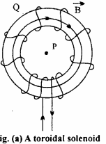
The direction of magnetic field in – side is clockwise as per the right hand thumb rule for circular loops. Three circular Amperian loops are shown by dashed lines.
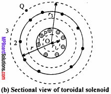
By symmetry, the magnetic field should be tangential to them and constant in magnitude for each of the loops.
1. For points in the open space interior to the toroid:
Let B1 be the magnitude of the magnetic field along the Amperian loop 1 of radius r1
Length of the loop L1 = 2πr1
As the loop encloses no current, I = 0
Applying Ampere’s circuital law.
B1L1 = μ0I
or B12πr1 = μ0 × 0
Thus, the magnetic field at any point P in the open space interior to the toroid is zero.
2. For points inside the toroid:
Let B be the magnitude of the magnetic field along the Amperian loop 2 of radius r.
Length of loop 2, L2 = 2π r
If N is the total number of turns in the toroid and I the current in the toroid, then total I the current enclosed by the loop 2 = NI.
Applying Ampere’s circuital law.
B × 2πr = μ0 NI
or B = \(\frac { { μ }_{ 0 }NI }{ 2πr }\)
If r be the average radius of the toroid and n the number of turns per unit length, then
N = 2πrn
∴ B = \(\frac { { μ }_{ 0 }I }{ 2πr }\).2πrn
or B = μ0I n.
3. For points in the open space exterior to the toroid:
Each turn of the torpid passes twice through the area enclosed by the Amperian loop 3. For each turn, the current coming out of the plane of paper is cancelled by the current going into the plane of paper.
Thus, I = 0 and hence B3 = 0.
Question 4.
Write four similarities between Biot – savart law and coloumb’s inverse square law.
Answer:
The four similarities between both are :
- Both laws obey inverse square law.
- Wide range of field is given by both the law’s.
- Principle of superpositions held for both the law.
- Both the law is effected by the medium of surrounding of the conductor.
![]()
Question 5.
State and prove Ampere’s circuital law.
Answer:
Ampere’s circuital law:
Ampere’s circuital law states that the line integral of magnetic field B around any closed path is equal to μ0 times the total current I enclosed by the path.
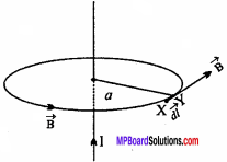
Mathematically \(\oint { \vec { B. } } \vec { dl }\) = µ0I
Proof:
Consider an infinitely long straight conductor carrying current I. The magnetic lines of force are produced around the conductor as concentric circles.
The magnetic field due to this current – carrying infinite conductor at a distance a is given by
B = \(\frac { { μ }_{ 0 } }{ 4π }\) \(\frac {2I}{a}\), … (1)
(from Biot – Savart law)
Consider a circle of radius a. Let XY be a small element of length dl. \(\vec { dl }\) and \(\vec { B }\) are in
the same direction because direction of [/latex] and \(\vec { B }\) is along the tangent to the circle.
The line integral for the closed path will be
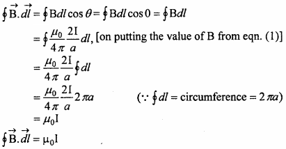
This proves Ampere’s circuital law.
Question 6.
Obtain an expression for the magnetic field due to a long straight current carrying conductor using Ampere’s circuital law.
Answer:
Consider an infinite long to conductor XY carrying current I as shown in the figure.
Magnetic field at P has to be found out. Distance between P and the wire is ‘a’. Draw an Amperian loop of radius a. Consider a line element RS = \(\vec { dl }\).
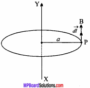
Let \(\vec { B}\) be the magnetic field at P; then the line integral of magnetic field along the circular path = \(\oint { Bdl }\) By Ampere’s circuital law,
\(\oint { Bdl }\) = µ0
Where, I is the total current flowing in the Amperian loop.
Angle between \(\vec { B }\) \(\vec { dl }\) = 0
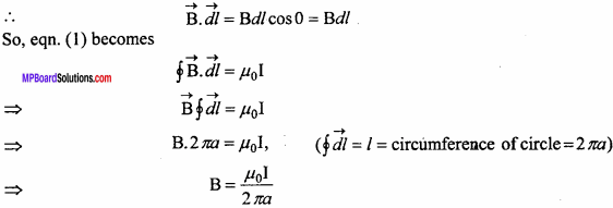
This is the strength of the magnetic field due to the conductor at a distance a.
![]()
Question 7.
Derive on expression for force acting on a current carrying conductor in a magnetic field.
Answer:
We know that a moving charge experiences a magnetic force in a uniform magnetic field. It can be extended for a current conductor placed in a uniform magnetic field, because electric current is the flow of free electrons. Let l be the length of a conductor, A its area of cross – section and n be the number density of free electrons.
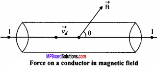
Then no. of free electrons in the conductor N=nAl
Let conductor be lying along Y – axis and magnetic field B lying in YY – plane makes angle 6 with Y – axis. Current flows through the coil along the direction of X – axis. Electric current flows through a conductor due to unidirectional flow of free electrons. Therefore, magnetic force acting on each free electron
\(\oint { f }\) = -e\((\vec { { v }_{ d } } \times \vec { B } )\)
Where \(\vec { { v }_{ d } }\) is the drift velocity of electron and e is the charge on an electron. Therefore, total magnetic force acting on the conductor
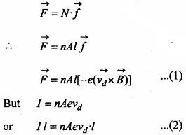
I \(\vec { l }\) is a current element directed along the direction of current. I \(\vec { l }\) and vd are directed in opposite directions. Therefore, eqn. (2) may be written as
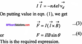
Case I : If θ = 0° , then sinθ = sin 0° = 0
Then from eqn. (4), F = 0
Thus, no magnetic force acts on a current carrying conductor lying parallel to magnetic field.
Case II : If θ = 90° ⇒ sinθ = sin90° = 1
Then p = JlB sin 90° or F = IlB (maximum)
Thus, a current carrying conductor placed perpendicular to a magnetic field experiences maximum magnetic force.
Question 8.
State Fleming’s left – hand rule.
Answer:
Stretch the forefinger, the middle finger and the thumb of your left – hand so that they are mutually perpendicular to each other. If the forefinger points the direction of magnetic field, the middle finger points the direction of current then the thumb indicates the direction of force acting on the conductor.
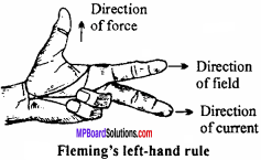
Question 9.
For circular motion of a charged particle in a uniform magnetic field obtain the expression for radius of path and periodic time of revolution.
Or
Discuss the motion of the charged particle in a uniform magnetic field with the initial velocity perpendicular to magnetic field.
Answer:
Consider a charged particle with charge q which is moving with a velocity v in a magnetic field of intensity B. Then, the maximum Lorentz force acting on the charged particle will be
F = qvB
and the direction of the force is perpendicular to v and B which is according to Fleming’s left – hand rule. So, no work will be done by the force on the charge because d W = Fd cosθ, here 0= 90°, hence d W = 0. It means that kinetic energy or the speed of the charged particle will be constant. So, the charge will move on a circular path.
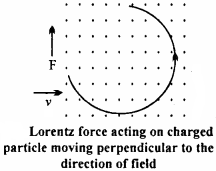
Now, for circular motion Lorentz force provides the necessary centripetal force.
Let the mass of the charged particle be m and the radius of circular path be r.
Then, Lorentz force = Centripetal force
or qvB = \(\frac { { mv }^{ 2 } }{ r }\)
or r = \(\frac { mv}{ qB }\) … (1)
or r = \(\frac { p}{ qB }\) … (2)
Where, mv = p = Momentum of the particle.
Hence, from eqn. (2), the radius of circular path is directly proportional to the momentum.
Again, angular velocity, w = \(\frac { v}{ r }\) = \(\frac { qB}{ m }\)
Frequency, v = \(\frac { w}{ 2π }\) = \(\frac { qB}{ 2πm }\)
and T = \(\frac { 1}{ v }\)
= \(\frac {2πm}{qB}\)
Question 10.
When the current flows in opposite direction in two parallel wires, both repel each other, why?
Answer:
If direction of current are opposite in the conductor then according to Fleming left hand rule the direction of force acting on the conductor CD will be in the plane of the paper and opposite to conductor AB. The direction of force acting on AB due to CD will be perpendicular to AB and opposite to CD on the plane of paper. Obviously the conductor will be repel each other.
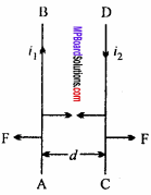
Question 11.
When the current flows in the same direction in two “ parallel wires. Both attract each other, why?
Answer:
In the direction of the current in both the conductors are same, then according to Fleming left hand rule, the direction of force acting on the conductor CD carrying current will be in the plane of paper perpendicular to conductor CD toward the conductor AB on the other hand the direction of force acting in conductor AB will be in the plane of paper perpendicular to conductor AB toward the conductor CD. Obviously the conductor AB and CD will attract each other.

Question 12.
Given two parallel wires carrying currents I1 and I2 are kept at a distance d apart. Obtain the expression for force exerted by one on (nt length of another. When will this force be attractive and when will it be repulsive?
Answer:
Let AB and CD be two parallel conductors kept at a distance d apart, current flowing through them is I1 and I2 respectively.
A magnetic field due to current I, is produced around AB.
∴ Intensity of magnetic field due to AB at a distance d is
B1 = \(\frac { { \mu }_{ 0 } }{ 4\pi } .\frac { { 2I }_{ 1 } }{ d }\) Wb/m2
According to right – hand palm rule, the direction of this field is downwards, normal to the plane of the paper.
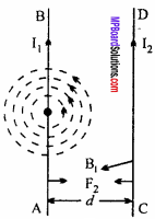
If another conductor CD carrying current I2 in the same direction of I1 is situated in the magnetic field of AB, then force on length l of CD is given by
F = I2 /B1 sin 90° = I2/B1
or F = I2l.\(\frac { { \mu }_{ 0 } }{ 4\pi } .\frac { { 2I }_{ 1 } }{ d }\)
or F = \(\frac { { \mu }_{ 0 } }{ 4\pi } .\frac { { 2I }_{ 1 }{ I }_{ 2 }l }{ d } \).
Force acting per unit length on CD will be
\(\frac { F}{ l }\) = \(\frac { { \mu }_{ 0 } }{ 4\pi } .\frac { { 2I }_{ 1 }{ I }_{ 2 }}{ d } \).
This is the required expression.
The direction of magnetic field B, on wire CD is acting inwards. Hence, by Fleming’s left – hand rule, the force F2 acting on CD will be directed towards AB, hence CD will come near to AB. So, the conductors attract each other, [see Fig. (a)] And when the current flows in opposite direction, they will repel each other, [see Fig. (b)].
Question 13.
Obtain an expression for the torque or the couple acting on a current loop, when it is placed in a magnetic field.
Or
Prove that the torque \(\oint { τ }\) acting bn a rectangular loop is given by \(\oint { τ }\) = \(\oint { m }\) \(\oint { B }\), where \(\oint { m}\) is the magnetic moment of the loop.
Answer:
Consider a rectangular coil ABCD of length ‘l’ and breadth ‘ b’ kept in a magnetic field of strength \(\oint { B }\). Let I be the amount of current flowing through the coil.
Force acting on AB is F1 = BI/sin90° = BIL. By Fleming’s left hand rule, it comes out of the plane of paper.
Force acting on CD is F2 = Bl/ sin 90° = Bll. By Fleming’s rule, it goes into the plane of paper.
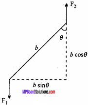
The forces, F1 and F2 are equal in magnitude but act along different line of action, hence they constitute a torque or couple.
At any instant of time, the normal to the coil makes an angle θ w.r.t. magnetic field B. The perpendicular distance between the forces F1 and F2 is bsinθ.
Torque acting on the coil is
τ = Magnitude of force × Perpendicular distance between the forces
= BIl x b sinθ
= BI(lb)sinθ
τ = BIAsinθ (∵ lb = A = area of coil)
If the coil consists of N circles, then
τ = NBIAsinθ
This is the expression for the torque acting on a current loop when placed in a magnetic field.
But NIA = m, the magnetic moment of loop.
So τ = mBsinθ
In vector notation, torque r is given by
\(\oint { τ }\) = \(\oint { m }\) \(\oint { B }\), where \(\oint { m}\)
The direction of the torque r is such that it rotates the loop clockwise along the axis of suspension.
Question 14.
Explain the construction of moving coil galvanometer by drawing its diagram; Why is a soft – iron core kept in the moving-coil galvanometer ? Why the pole pieces are made concave?
Answer:
1. A permanent strong horseshoe magnet is taken. Its pole pieces NS are made of cylindrical soft – iron, cut in concave shape. A coil A, is suspended between the pole pieces, by a phosphor bronze wire F. The other end of the coil is connected to a spring Sp. The coil consists of insulated copper wire wound on an aluminium frame and a soft iron cylinder C is fixed within the coil, so that the coil can freely turn around it.
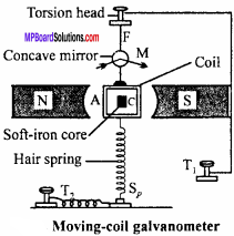
The wire F and spring Sp is connected to the terminals T1 and T2. Aconcave mirror M is attached to the wire F, so that the deflection of the coil can be measured with the help of lamp and scale arrangement. All the above arrangement is kept inside a non – magnetic box to protect it by dust, air, etc. The front portion of the box is made of glass and the base is provided by levelling screws.
2. Soft – iron core is used in moving coil galvanometer because :
- The permeability of soft – iron is very high, hence the field intensity increases.
- It makes the field radial.
3. By making pole pieces of magnet concave, the field is made radial, so that the plane of the coil becomes parallel to the magnetic field in all the positions.
Question 15.
Explain the principle of moving – coil galvanometer and find the expression for the current.
Or
What is the principle of moving – coil galvanometer? Prove that the current is proportional to the deflection of the coil.
Answer:
Principle:
Whenever a current is made to pass through a coil placed in a uniform magnetic field, then a torque acts on it which rotates the coil and tries to make it perpendicular to the direction of the field. Let ABCD be a rectangular coil, which is kept in a magnetic field B. such that the sides AB and CD are perpendicular, to field. Let the length of the coil AB be l and breadth BC be b. If I is the current flowing in the coil, then Lorentz force acting on AB and CD will be F = BIl.
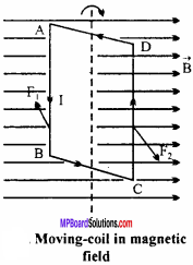
The force acting on AB is F1 which comes out of the plane of paper and on CD is F2 which goes inside the plane of paper. As the forces are equal in magnitude and opposite in direction along different line of action, hence they produce a couple.
At any instant of time, the axis of coil (i.e., the normal to the coil) makes an angle θ with respect to the magnetic field, then the perpendicular distance between two forces F1 and F2 is bsinθ.
Now, torque = Magnitude of force x Perpendicular distance between two forces
= BIl × bsinθ = BIAsinθ
Where, A =lb = Area of the coil.
If N is the number of turns on the coil, then
τ = NBI Asin θ
Initially, when the plane of the coil lies parallel to the magnetic field, then the angle between the magnetic field and normal to the coil is 90°, i.e., θ = 90° therefore sinθ= 1.
∴τmax =NBIA
This torque is the deflecting torque. Which rotates the coil. As a result, a restoring torque gets developed in the suspension wire which tries to restore the coil back to the initial position.
Let ϕ be the angle of twist and C is the couple for unit twist.
Restoring torque produced = Cϕ
Under equilibrium, deflecting torque = Restoring torque.
∴ NBIA = Cϕ
or I = \(\frac {C}{NBA}\)ϕ
or I = kϕ (where, k = \(\frac {C}{NBA}\)
or I ∝ϕ
This is the principle of moving – coil galvanometer.
![]()
Question 16.
What do you understand by the sensitivity of moving – coil galvanometer? Write its expression. On what factors does it depend and how?
Answer:
The current sensitivity of a moving coil galvanometer is defined as the deflection produced by unit current through the coil.
Let ϕ be the deflection produced due to current I, then
I = \(\frac {C}{NBA}\)ϕ
If the current through the galvanometer is I, which produces a deflection ϕ, then
\(\frac {ϕ}{I}\) = \(\frac {NBA}{C}\)
Sensitivity of galvanometer s = \(\frac {ϕ}{I}\)
= \(\frac {NBA}{C}\)
Sensitivity depends on the following factors :
- N (No. of turns) should be greater. As the nufnber of turns increases, sensitivity increases.
- For greater sensitivity, magnetic field should be greater. To increase the magnetic field B, a permanent horseshoe magnet must be used. By increasing B, sensitivity increases.
- Area of the coil : If area increases, sensitivity increases.
- C (Couple per unit twist) : The value of C should be less for more sensitivity.
Question 17.
What is meant by shunt? If the resistance of a galvanometer is Rg, then calculate the value of the shunt carrying current nth part of total current to pass through the galvanometer.
Answer:
Shunt:
A shunt is a thick copper wire which is joined in parallel with the coil of the galvanometer. It has very low resistance.
Let Rg be the resistance of galvanometer and S be the value of the shunt resistance.
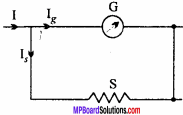
Let I be the total current flow in the circuit. It gets divided as Ig and Is: where Ig is the current flowing in galvanometer and I, in the shunt resistance (S).
∴ I = Ig + Is … (1)
Now, potential difference across galvanometer = Ig.Rg
and Potential difference across shunt = Is.S.
As galvanometer and shunt are in parallel, hence potential difference will be equal
i.e.,
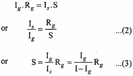
This is the value of shunt resistance.
Adding 1 to both sides of eqn. (2), we get
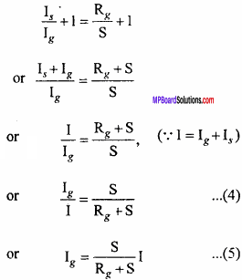
The above equation gives the value of current flow through the galvanometer in turns of total current.
If the current passing through the galvanometer is nth part of the total current, then
\(\frac { { I }_{ g } }{ I }\) = \(\frac {1}{n}\)
Eqn. (4) becomes
\(\frac {1}{n}\) = \(\frac { s }{ { R }_{ g }+S }\)
or nS = Rg + S
or nS – S = Rg
or S(n -1) = Rg
or S = \(\frac { { R }_{ g } }{ (n-1) }\) … (6)
Hence, for the nth part of total current to pass through the galvanometer, the resistance of the shunt should be (n – l)th of the resistance of galvanometer.
Question 18.
How a galvanometer can be converted to ammeter and voltmeter?
Answer:
Conversion of galvanometer into ammeter:
Since, the coil of the galvanometer has low resistance, so to convert it into ammeter, a low resistance (called shunt) is joined in parallel, so that most of the current passes through the shunt and very less current passes through the coil of galvanometer.
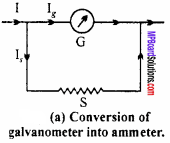
Derive up to eqn. (3) from Short Ans. Type Q. No. 17.
Hence, by joining a shunt resistance of value
S = \(\frac { { I }_{ g }{ R }_{ g } }{ I-{ I }_{ g } }\)
So, the galvanometer gets converted to an ammeter.
Conversion of galvanometer into voltmeter:
The resistance of voltmeter is high, So to convert a galvanometer into a voltmeter, a high resistance wire is connected wire is connected in series to the coil of galvanometer, [see fig.(b)].

Suppose Rg be the resistance of galvanometer and R is the resistance of wire connected A in series. Let I be the current flowing in the galvanometer.
In order to convert a galvanometer into a voltmeter of range (0 – V) volts, we have from adjacent figure
The total potential difference between A and B will be
V = Ig(Rg + R)
or Rg + R = \(\frac { V }{ { I }_{ g } }\)
or R = \(\frac { V }{ { I }_{ g } }\) – Rg.
This is the expression and the value of the resistance required to convert the galvanometer to voltmeter of range 0 to V.
Question 19.
What is a shunt? Write its uses. What are advantages and disadvantages of shunt?
Answer:
Shunt:
It is a wire of low resistance, connected in parallel to the coil of a galvanometer.
Uses:
A galvanometer is converted into an ammeter by using a shunt.
Advantages:
- It protects the coil of the galvanometer from burning as well as the breaking of the pointer.
- As the shunt is connected in parallel, the resultant resistance becomes less. So, when the shunted galvanometer (ammeter) is joined in series, then the value of the current does not change.
Disadvantages:
Due to shunt, the sensitivity of galvanometer is reduced. So, it should be removed from the galvanometer when we have to obtain null point.
Moving Charges and Magnetism Long Answer Type Questions
Question 1.
Derive an expression for the intensity of magnetic field at a point on the axis of a circular current loop.
Or
Obtain an expression for the intensity of the magnetic field at a point on the axis of a circular coil.
Answer:
Magnetic field at a point on the axis of a circular current loop:
Let a be the radius of a circular loop and current 1 is flowing through it in the direction shown in the figure. A point P is considered on the axis of the loop, at a distance x from the centre O, at which the intensity of the magnetic field is to be determined.
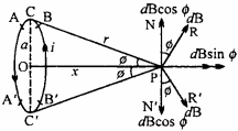
The plane of the loop is normal to the plane of the paper and its axis OP lies on the plane of the paper. Let the loop be divided into so many small elements, each of length dl, let one of such small part is AB.
∴ The intensity of the magnetic field at P, due to dl, is given by
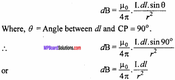
The direction of dB is along PR, normal to CP. Let ∠CPO = ϕ
Resolving dB in two parts, we get
- dB sinϕ, along OP and
- dB cosϕ, along PN, normal to OP.
If another small element dl is considered, diametrically opposite to AB, i.e., A’B’.
∴ Intensity of magnetic field at P, due to A’B’ will be
dB = \(\frac { { \mu }_{ 0 } }{ 4\pi } .\frac { I.dl }{ { r }^{ 2 } }\)
Again, resolving dB, we get
- dB sin0, along OP and
- dB cos0, along PN’, normal to OP.
As the directions of PN and PN’, are opposite, hence they will cancel the effect of each other. Similarly, all the resolved parts, perpendicular to OP will be cancelled out. But the components along the direction AP, will be summed up.
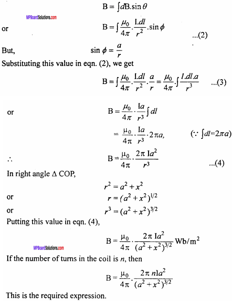
∴ Intensity of magnetic field due to the circular loop at point P will be
Question 2.
State Biot – Savart law and with the help of it derive an expression for magnetic field intensity at a point situated at a distance from a current carrying straight wire of infinite length.
Answer:
Biot – Savart law:
Let AB be a conductor carrying current I. Consider a small line element dl of the conductor, due to which the magnetic field dB is produced at point P, then the strength of the magnetic field \(\vec { (dB) }\) depends on the following factors :
(i) The field is directly proportional to current I.
i.e., dB ∝I
(ii) The field is directly proportional to the length of element,
i.e., dB ∝ dl
(iii) The field is directly proportional to the sine of angle between the line joining the point and dl.
i.e., dB ∝ sinθ
(iv) The field is inversely proportional to the square of the distance between the observation point and line element.
i.e.,
dB ∝ \(\frac { 1 }{ { r }^{ 2 } }\)
Combining all the four points,we get
dB ∝ \(\frac { Idl sinθ }{ { r }^{ 2 } }\)
or dB ∝ K\(\frac { Idl sinθ }{ { r }^{ 2 } }\) … (1)
Where, K is constant of proportionality. Its value depends upon the system of units
In C.G.S system, k = 1
∴ dB ∝ K\(\frac { Idl sinθ }{ { r }^{ 2 } }\) gauss … (2)
In M.K.S. system, K = \(\frac { { μ }_{ 0 } }{ 4π }\)
Where, μ0 = Permeability of free space.
∴ dB = \(\frac { { μ }_{ 0 } }{ 4π }\) \(\frac { Idl sinθ }{ { r }^{ 2 } }\) Wb/m2 … (3)
or dB =10-7 [/latex] \(\frac { Idl sinθ }{ { r }^{ 2 } }\) Wb/m2 … (4)
The relations given by eqns. (2), (3) and (4) are called Biot – Savart law.
The direction of the magnetic field \(\vec { dB }\) is always perpendicular to the plane containing \(\vec { dl }\) and \(\vec { r }\) and is given by the right – hand screw rule for the cross product of vectors.
Unit of electric current:
1. In C.GS. system : If dl= 1cm, r= 1cm, sinθ = 1 i.e., 9 = 90° and dB = 1 gauss, then from eqn. (2) I = 1 electromagnetic unit (e.m.u.).
For 9= 90°, the conductor should be taken as a part of circle, as the radius is always perpendicular to the circumference. Thus, 1 e.m.u. of current is that current which produces a field of 1 oersted at the centre of the conductor of length 1 cm, kept in the form of an arc of a circle of radius 1 cm.
2. In M.K.S. system: If dl =1m, r = 1m, sinθ = 1 and dB = 10-7 Wb/m2, then from eqn. (4)
I = 1 ampere.
Thus, 1 ampere of current is that current which produces a field of 10-7 Wb/m2, at the centre of tWconductor of length 1m.
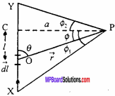
Consider a long straight conductor XY which is on the plane Y of paper and current flow through it is I, which flows from X to Y. c Then magnetic field has to be found at position P, which is situated t at a distance a (distance measured perpendicularly from the wire) from the wire.
∴PC = a
To find out the total magnetic field at P, we have to first find out the magnetic field due to small line element \(\vec { dl }\), which is situated at a distance l from C. On integrating the magnetic field due to line element \(\vec { dl }\) , we can get the total magnetic field.
Let \(\vec { r }\) be the position vector of P with respect to the line element \(\vec { dl }\) and θ is the angle
between the line element \(\vec { dl }\) and \(\vec { r }\).
By Biot – Savart law,
dB = \(\frac { { \mu }_{ 0 } }{ 4\pi } .\frac { I.dl }{ { r }^{ 2 } }\)
We have to find out the magnetic field due to line element \(\vec { dl }\) at P, which is situated at r from \(\vec { dl }\) . The position of \(\vec { dl }\) can vary, hence θ can change, so we have to find out the value of sinθ and dl. For that, consider right angled triangle POC.
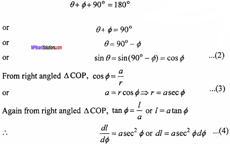
Putting the values of sinθ, r and dl from eqns. (2), (3) and (4) respectively in eqn. (1), we get

Eqn. (5) is the magnetic field due to line element dl. To find out the total magnetic field, integrating both sides under limits from ϕ1 to ϕ2 (-ϕ1 is taken because it is clock wise or below the line joining CP and ϕ2 is taken because it is anticlockwise or above the line joining CP).
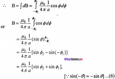
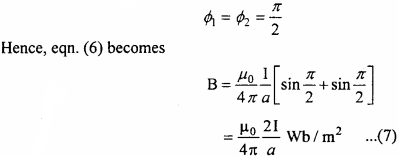
For an infinitely long conductor and if the observation point is very near, then
Question 3.
Describe the cyclotron under the following points :
- Construction
- Principle and working process.
Or
What is a cyclotron? Write its principle. Obtain the expression for the cyclotron frequency and the maximum energy of the charged particle when it hits the target.
Answer:
Principle:
It is based on the principle that when a positively charged particle is made to move again and again in a high frequency electric field and using strong magnetic field, then it gets accelerated and acquires sufficiently large amount of energy.
Construction:
It consist of two hollow D – shaped metallic chambers D1 and D2 called dees. These dees are separated by a small gap where a source of positively charged particle is placed. Dees are connected to a high frequency oscillator, which provide high frequency electric field across the gap of the dees. This arrangement is placed between two poles of a strong electromagent. The magnetic field due to this electromagnet is perpendicular to the plane of the dees.
Working:
If a positively charged particle (proton) is emitted from O, when D2 is negatively charged and the dee D1, is positively charged, it will accelerate towards D2. As soon as it enters D2, it is shielded from the electric field by metallic chamber (enclosed space). Inside D2, it moves at right angles to the magnetic field and hence describes a semi – circle inside it. After completing the semicircle, it enters the gap between the dees at the time when the polarities of the dees have been reversed.
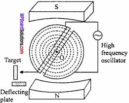
Now, the proton is further accelerated towards D1. Then it enters D1 and again describes the semicircle due to the magnetic field which is perpendicular to the motion of the proton. This motion continues till the proton reaches the periphery of the dee system. At this stage, the proton is deflected by the deflecting plate which then comes out through the window and hits the target.
Theory:
When a proton (or any other positively charged particle) moves at right angle to the magnetic field B inside the dees, Lorentz force acts on it.
i. e., F = qvB sin 90° = qvB
Where, q = Charge of particle and v = Velocity of particle.
The force provides the necessary centripetal force \(\frac { m{ v }^{ 2 } }{ r }\) to the charged particle to move in a circular path of radius r.
∴ qvB = { m{ v }^{ 2 } }{ r }[/latex]
or r = \(\frac {mv}{qB}\) … (1)
Time taken to complete one semicircle inside a dee,
t = \(\frac {Distance}{Speed}\) = \(\frac { πr}{v}\)
or t = \(\frac { π}{v}\) × \(\frac { mv}{qB}\) [from eqn.(1)]
t = \(\frac { πm}{qB}\) … (2)
Thus, time taken to complete one semicircle does not depend upon radius of path. If T is the time – period of the alternate electric field, then the polarities of the dees changes in time 772.
i.e., \(\frac {T}{2}\) = t = \(\frac {πm}{qB}\)
or T = \(\frac {2πm}{qB}\) … (3)
So, cyclotron frequency or magnetic resonance frequency,
v = \(\frac {1}{T}\) = \(\frac {qB}{2πm}\) … (4)
Energy gained by a positively charged particle is given by
E = \(\frac {1}{2}\)mv2
From eqn (1), v = \(\frac {qBr}{m}\)
so, E = \(\frac {1}{2}\)m\(\frac { { q }^{ 2 }{ B }^{ 2 }{ r }^{ 2 } }{ { m }^{ 2 } } \)
= \(\frac { { q }^{ 2 }{ B }^{ 2 }{ r }^{ 2 } }{ { 2m } }\)
Maximum energy is gained by the positively charged particle when it is at the periphery of the dees (r is maximum), i.e.,
Emax = \(\frac { { q }^{ 2 }{ B }^{ 2 } }{ { 2m } }\) r2max
![]()
Question 4.
Obtain an expression for magnetic field due to a solenoid using Ampere’s circuital law.
Answer:
Consider a very long solenoid having n turns per unit length carrying current I. The magnetic field inside the solenoid is uniform and directed along the axis of solenoid.
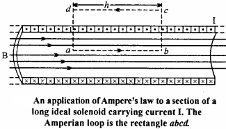
Consider a rectangular Amperian loop abed in a solenoid. Magnetic field B is uniform within the solenoid. Let the length of the Amperian loop be h.
∴Total number of turns in Amperian loop = nh.
The integral \(\oint { \vec { B } .\vec { dl } }\) is basically equal to the sum of four integrals
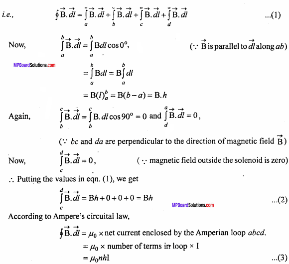
Comparing eqns.(2) and (3)
Bh = µ0nhI
⇒ B = µ0nI.
Question 5.
Explain the experiment to find reduction factor of a tangent galvanometer under following points :
- Formula
- Circuit diagram
- Observation table
- Any two precautions.
Answer:
1. Formula : i = ktanθ or k = \(\frac {i}{tanθ}\)
Where i = Current flowing through coil, and
θ = Deflection in magnetic needle.
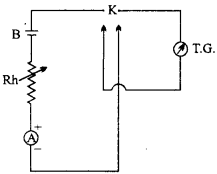
2. Circuit diagram :
TG = Tangent Galvanometer,
K = Reversing key,
B = Cell, Rh = Rheostat,
A = Ammeter.
3. Observation table:

4. Precautions :
There should be no magnet near tangent galvanometer.
After aligning in magnetic meridian, the tangent galvanometer should not be moved.
Moving Charges and Magnetism Numerical Questions
Question 1.
The frequency of a cyclotron oscillator is 10 MHz.What should be the magnetic field required to accelerate a proton (e = 1.6 x 10⁻¹⁹C, m =1.67 x 10⁻²⁷kg)
Solution:
f = \(\frac {qB}{2πm}\)
or B = \(\frac {2πmf}{q}\)
Given : m = 1.67 x 10⁻²⁷kg, f = 10 x 106Hz, q = e = 1.6 x 10⁻¹⁹
![]()
Question 2.
A particle having 100 times charge of an electron is revolving in a circle of radius 0-8 metre in each second. Calculate the intensity of magnetic field.
Solution:
Formula: B = \(\frac { { \mu }_{ 0 } }{ 4\pi } .\frac { 2\pi I }{ R }\)
Given : q = 100 x 1.6 x 10-19
= 1.6 x 10⁻¹⁷ coulomb, R = 0.8 metre
Putting the value in formula, we get I = \(\frac {q}{t}\)
\(\frac { 1.6\times { 10 }^{ -17 } }{ 1 }\) = 1.6 x 10⁻¹⁷
B = \(\frac { { \mu }_{ 0 } }{ 4\pi } .\frac { 2\pi \times 1.6\times { 10 }^{ -17 } }{ 0.8 }\) or B = 10-2µ0
Question 3.
Calculate the torque on a 20 turns square coil of side 10 cm carrying a current of 12 A, when placed, making an angle of 30° with the magnetic field of 0.8 T.
Solution:
Given : A = 100cm2 100 x 10-4m2 = 10-2m2 n = 20, I = 12A, B = 0.8T, ϕ = 30°
Formula: τ = nIABsinϕ
= 20 x 12 x 102 x 0. 8sin30°
= 20 x 12 x 0.8 x 102 x \(\frac {1}{2}\)
= 96 x 102 = 0.96 N – m.
![]()
Question 4.
Resistance of a Galvanometer is 50 ohms, when 0.01 Acurrent flows through it, full scale defections is obtained. How it can be converted into
- 5 A range ammeter and
- 5 volts range voltmeter.
Solution:
1. Given : G = 50 ohm, ig = 0.01 A, I = 5A
Formula : S = \(\frac { { I }_{ g }G }{ I-{ I }_{ g } }\)
Putting the value in the formula are get = \(\frac {0.01 x 50}{5-0.01}\) = \(\frac {0.5}{4.99}\)
2. Given : V = 5 vol
Formula : R = \(\frac { V }{ { I }_{ g } }\) – G
Putting the value in the formula are get
R = \(\frac {5}{0.01}\) – 50 = 500 – 50 = 450 ohms.
Question 5.
Find the magnitude of magnetic field at the centre of a circular coil of radius 10 cm having 100 turns. Current flowing through the coil is 1A. (NCERT Solved Example)
Solution:
Given, R = 10 cm = 10 x 10-2m; N = 100; I = 1A;
B = \(\frac { { \mu }_{ 0 }NI }{ 2R }\) = \(\frac { 4\pi \times { 10 }^{ -7 }\times 100\times 1 }{ 2\times 10\times { 10 }^{ -2 } }\)
B = 2π x 10-4
= 6.28 x 10⁻⁴ tesla.
Question 6.
10 A current is flowing through a straight conductor. Determine the intensity of magnetic field at a distance 10 m from it.
Solution:
Formula :B = \(\frac { { \mu }_{ 0 } }{ 4\pi } .\frac { 2I }{ d }\)
Given: I = 10 Aandd = 10m.
Substituting the values in the formula, we get
B = 10-7 x \(\frac {2×10}{10}\)
∴B = 2 x 10⁻⁷Wb/m2.
Question 7.
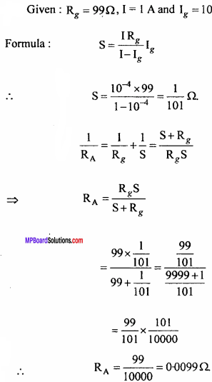
An ammeter of resistance 99 Ω, gives full – scale deflection with 10-4A current. What arrangement is required to measure a current of 1A by it? Calculate the resistance of ammeter.
Solution:
Question 8.
A solenoid of length 0.5 m has a radius of 1 cm and is made up of 500 turns. It carries a current of 5A. What is the magnitude of the magnetic field inside the solenoid? (NCERT)
Solution:
Given, l = 0.5 m, r = 1 cm = 1 x 10⁻² m, N = 500; I = 5A Number of turns per unit length
Number of turns per unit length
n = \(\frac {N}{l}\) = \(\frac {500}{0.5}\)
Here l >> r
∴Magnetic field inside the solenoid
B = µ0nI
= 4π x 10-7 x \(\frac {500}{0.5}\) x 5
B = 6.28 x 10⁻³tesla.
![]()
Question 9.
A wire through which a current of 8A is flowing makes an angle of 30° with the direction of magnetic field of 0.15 tesla. Calculate the force acting per unit length of wire.
Solution:
Given : I = 8A, B = 0.15T, θ = 30°, F =?
formula: F = BIlsinθ
⇒ \(\frac {F}{l}\) = BIlsinθ
= 0.15 x 8 x sin30°
= 0.15 x 8 x \(\frac {1}{2}\) = 0.6N/m.
Question 10.
Two parallel wires A and B are carrying currents 10 A and 2 A respectively, in opposite directions. If the length of the wire A is infinite and length of B is 1 metre, calculate the force on B situated at a normal distance of 10 cm from A.
Solution:
Formula : \(\frac { { \mu }_{ 0 } }{ 4\pi } \frac { 2{ I }_{ 1 }{ I }_{ 2 } }{ d } \times l\)
= 10-7\(\frac { 2{ I }_{ 1 }{ I }_{ 2 } }{ d } \times l\)
Given : I1 = 10 A, I2 = 2A , l = 1 m, d = 0.1 m
∴ F = 10-7 × \(\frac {2×10×2×1}{0.1}\)
= 400 x 10-7= 4.0 x 10⁻⁵N.